
[ About | The Process | Rendering | Discussion ]
Whenever I need a highspeed adrenalin rush, I pop F-Zero into my SNES. This launch title demonstrated how graphics Mode 7, HDMA and some clever programming could create full screen, smoothly animated, visually stunning 2.5D effects. But, one thing has always bothered me about the racetrack: long parallel lines, such as the sides of the track, fail to converge at a vanishing point. For a comparison against the real world, check out at this a pic I took at High Line Park in lower Manhattan.

All edges of the concrete slabs making up the floor and the handrails converge to a common vanishing point on the horizon. Contrast this against the screenshots below.


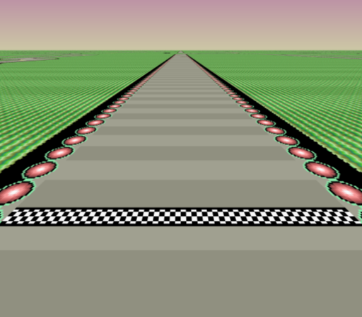
On the left is a screenshot of Death Wind. Notice that the track appears to be cutoff some distance away from the viewer. On the right, I drew red lines to illustrate where the vanishing point should appear. Of course, you could blame distance fog caused by atmospheric haze, aerial perspective and so on. But, as the blue line shows, the true horizon is quite a bit higher than the game suggests.
I wanted to know what the track would look with the real horizon restored. So, I did a bit of coding to find out.
High-resolution images of the F-Zero racetracks are available online. And, screenshots of the game can be obtained from emulators. The goal was to 3D render the racetracks to produce images as close to screenshots as possible.
One can certainly dig through the game code and figure out exactly how the camera operates, but that is currently beyond my skillset. Instead, I began by marking common pixels on the racetracks and the screenshots. See the red dots in the images below.
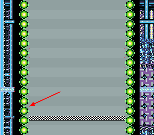

The dots are primarily along the inner edges of the track. In case you have trouble seeing them, I added arrows pointing to a common one.
Since the start/finish line is horizontal in both images, it's easy for a program to match up all the red dots.
The next step was to work out the parameters of the virtual camera. It’s floating at a fixed height above the ground, facing perpendicular to the start/finish line. The horizontal horizon indicates that the camera has no roll. However, since the horizon appears above center frame, the camera must be tilted downward as shown below.

The point e is the eye of the camera. It’s analogous to the tiny aperture of a pinhole camera or a camera obscura. The eye hovers a distance h above the ground. And, from its point of view, the screen acts like a glass window through which it can see the 3D world. The center of the screen, c, is a distance D in front of the eye. And, the camera tilt, θ, is the angle between that screen center line and the horizontal axis.
Since light follows a straight line, the camera eye cannot differentiate between a point on the screen, p, and a corresponding point on the ground, g. The vector (g − e) is equal to (p − e) scaled by some constant s:
g − e = s (p − e)
(1)
If the ground is the xz-plane, where y = 0 for all points, then the y-components of the vectors can be expressed as:
0 − ey = s (py − ey)
(2)
This can be rearranged to solve for s:
s = ey / (ey − py)
(3)
s can be plugged back into Eq. (1) to map a point on the ground to a point on the screen or vice versa. Also, note that since the figure above depicts the screen on edge, the solved s is applicable to all points along a horizontal scanline. In fact, from Eq. (1), moving along a scanline is equivalent moving along a line on the ground at a rate scaled by s from the eye’s point of view. In other words, a scanline could be rendered by scaling a particular line of pixels from the ground by the constant s.
Let t represent the scanline index relative to the center of the screen; i.e. the center scanline is t = 0 and t can be positive or negative. The vector (p − c) can be defined in terms of t and θ:
p − c = t (sin(θ), cos(θ))
(4)
Similarly, the vector (c − e) can be defined in terms of D and θ:
c − e = D (cos(θ), −sin(θ))
(5)
Eq. (4) and Eq. (5) can be combined to express p from t, D and θ:
p = e + D (cos(θ), −sin(θ)) + t (sin(θ), cos(θ))
(6)
Hence, for each scanline, it’s possible to locate the corresponding line on the ground and its associated scale. Well, almost. That works for the area of the screen below point z. Everything above it is sky.
Using these equations and a given set of camera parameters, the red dots on the racetrack can be projected and compared against the red dots on the screenshot. The distance between them is a measure of error and several optimization algorithms exist that can iteratively find parameters that minimize this error. For this project, this was accomplished using particle swarm optimization (PSO). It was applied for the red dots of 6 racetracks simultaneously to obtain parameters that perform optimally across all of them.
Here are the results:
| Parameter | Value |
|---|---|
| h | 50.6968616564420100 |
| D | 112.6447071647171800 |
| θ | 0.5948644078824534 |
The distances h and D are in pixel units; i.e. they are in the same scale as the high-resolution racetrack images and the dimensions of the camera viewport is SNES screen resolution (256 × 224). The tilt angle, θ, is in radians.
This iterative approach is only capable of producing an approximation of the actual values. The real values are probably closer to round numbers. If I had to guess, the real camera height, h, is likely 50, the real viewport distance, D, is likely 112 (half the screen height), and the real camera tilt, θ, is likely 35°. But, for rendering, I used the values directly provided by the PSO algorithm.
PSO also worked out the full camera eye coordinates for the 6 racetracks. For example, in the image below, the red dot marks where the eye floats above the track, the red line is the center scanline of the viewport and the blue line is the false horizon, which is only 613 pixels away from the eye.

Using the equations above, I wrote a program to ray cast the 6 racetracks at twice SNES resolution and with 1024 samples per pixel. The high-resolution racetrack images were extended to infinity in all directions by tiling and the sky is a simple gradient based off colors from the screenshots.


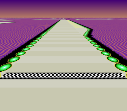

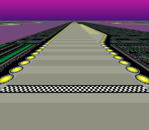
Some of the landscape looks a bit different in the final rendered image due to the way that the high-resolution racetrack image is cropped and the way that the renderer tiles it.
Why does F-Zero present false horizons? Here are some possibilities:
Copyright © 2018 meatfighter.com